Table Of Content
- How To Determine The Perfect Size For Your Grease Trap: A Simple Guide
- Why Choose Neville Engineering Oil and Grease Trap Designs?
- Select Grease Trap Type and Size
- Learn How To Design A Grease Trap Like A Pro! Simple Steps To A Cleaner Kitchen
- Stop Clogging With Stellar Interceptor Design
- Choose Efficiency for Oil-Water Separation Design
These mechanisms are time-dependent, so the design of the tank must allow for an appropriate amount of retention time and for a calm environment beneath the liquid level. Velocity spikes must be minimized to allow for separation and to avoid potential interaction with previously separated FOG or solids layers. The accumulation of FOG and solids layers will effectively reduce the clear zone and will result in slightly accelerated velocity of fluid through the tank. This reinforces the importance of periodic maintenance and cleaning of the tank.
How To Determine The Perfect Size For Your Grease Trap: A Simple Guide
The effectiveness of the compartments depends on the connection hole or baffle system. The tank can be made in different shapes and configurations, but must be effective in intercepting the grease. If sufficient amounts of FOG enter the sewer pipes, the resulting product will begin to collect on the top and sides of the pipe. As flow continues, more grease becomes trapped and the buildup continues until the flow is significantly restricted. They also exhibit exceptional durability and can withstand the corrosive effects of oil and grease over an extended period.
Why Choose Neville Engineering Oil and Grease Trap Designs?
They also shift the maintenance responsibility from kitchen staff to third-party maintenance contractors, providing additional quality and safety assurance. As such, precast concrete GGIs are an efficient solution to a critical challenge, offering peace of mind to environmental professionals and facility owners. A properly functioning precast concrete GGI is key to keeping FOG-related issues from occurring in the treatment field or sewer system. While flow rate is important in sizing, it is not the only factor that should be considered. Designing the tank to provide ease of maintenance while also maximizing retention time and creating a quiescent environment is essential for separation effectiveness.
Select Grease Trap Type and Size
Our grease interceptor sizing maximizes efficiency and ensures adequate grease retention capacity. With customized sizing from us, establishments can maintain problem-free drains and plumbing while meeting all code requirements. Oil and grease traps intercept and separate most greases and oils before they enter the wastewater collection system.
Our team provides necessary support and clarifications, making sure that every aspect of the design is properly translated into the final product. Based on the information gathered during the consultation, our team develops concept designs that showcase various possibilities for your GREASE TRAP design. We consider factors such as functionality, aesthetics, and compliance to create designs that align with your vision.
Wrap-Up: Empowering Effective Grease Trap Management
They are common fixtures in restaurants, food service establishments, institutions with kitchens, and other commercial facilities that produce significant amounts of animal fats, oils, and grease (FOG). As a specialized architectural firm in the field of heavy industry and engineering, we have in-depth knowledge of the specific requirements and complexities of GREASE TRAP design. Our team understands the importance of designing efficient and reliable grease traps to ensure optimal functionality and compliance with local regulations.
Stop Clogging With Stellar Interceptor Design
Applying this to XYZ Restaurant, the flow rate would drop to below 20 GPM, thus requiring a 750-gallon tank. Bring your commercial or multi-family building plans to life with Neville Engineering Service, Inc. Our experienced team provides expert heating, ventilating, air conditioning, plumbing, and electrical services to perfect your building’s performance. Our grease traps incorporate green technology, such as recycled steel content and energy-efficient manufacturing methods. Do not purchase a grease interceptor without obtaining a building plan approval including an Industrial Waste approval letter specifying the size and design of the interceptor that will be required. Purchasing an interceptor prior to IW approval exposes the purchaser to risk of rejection and replacement costs.
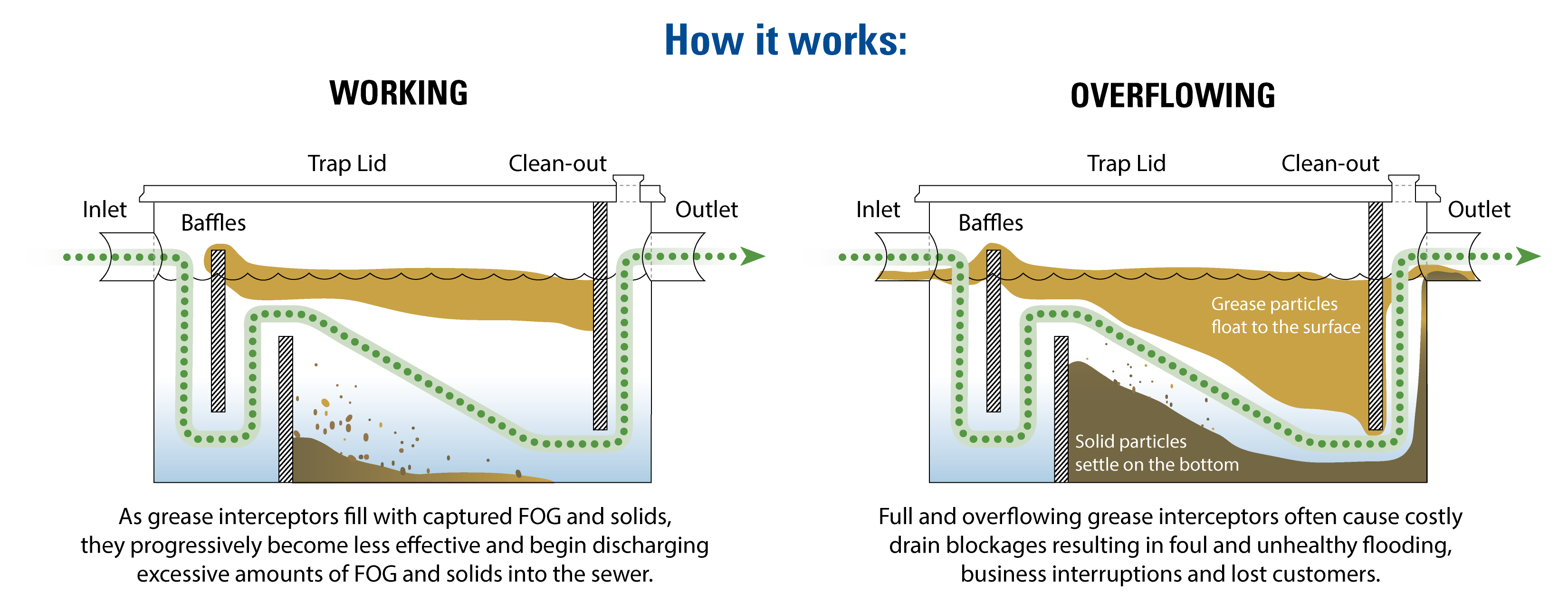
By following the guidelines outlined in this guide, you can design and install grease traps that meet the specific needs of your commercial kitchen. Proper design and maintenance ensure efficient FOG removal, preventing environmental pollution and costly issues in the wastewater system. Embrace the knowledge and techniques provided here to achieve optimal grease trap performance and maintain a compliant and environmentally sustainable operation. Grease traps are essential components in commercial kitchens, effectively preventing fats, oils, and grease (FOG) from entering the wastewater system.

However, the short-term impact of this density upflow is minor on the effluent FOG concentration. Over time, the effluent FOG concentration will be similar to previous uniform influent/bulk temperature results. If the density of the globule is less than the density of the fluid, the globule will rise at velocity V, and vice versa. If we were to divide that globule size in half to 100 microns (.00033 feet), the globule would rise at 0.002 ft./s. Therefore, for more effective separation, larger grease globules are optimal. The right sizing helps prevent sewer line clogs, equipment damage, and fines for non-compliance.
Prevent corrosion – Grease is acidic and can eat away at plumbing and sewer infrastructure if left uncontrolled. The goal for engineered GGIs is to closely comply to the concrete GGI requirements but allow slight flexibility if site conditions are not ideal for a concrete GGI. If DFUs are not known, Table 702.2a of UPC Chapter 7 (Table 3) can be used to assign values based on the maximum DFUs allowed for the pipe size connected to the inlet of the interceptor.
Ideally, the area would occupy the entire cross-section of the of the grease interceptor (i.e., depth times height), as this setup would provide the lowest fluid velocities. To achieve this, the influent baffle would have to be designed to distribute the incoming flow (Figure 3). Grease interceptors work to remove FOG and other materials through separation by gravity or flotation.
Pine Bluff agency to buy, develop downtown lot Arkansas Democrat Gazette - Arkansas Online
Pine Bluff agency to buy, develop downtown lot Arkansas Democrat Gazette.
Posted: Fri, 18 Nov 2022 08:00:00 GMT [source]
Tank designs should enhance the ability to clean and maintain the interceptor. Detergents used in today’s kitchens may contain emulsifiers to aid in the removal of FOG from dishware and kitchen utensils. Emulsifiers work to prevent FOG from coalescing by reducing the interfacial tension that makes grease globules attract.
Neville Engineering manufactures highly durable and long-lasting oil and grease separators. These separators can withstand the harshest environmental conditions and heavy usage in various industries. They prevent clogs and blockages in piping that can lead to wastewater overflows and backups. Grease traps have baffles and flow control fittings that retain the grease in a reservoir while allowing the greywater to flow to the wastewater system.
Our team works closely with you to understand your requirements, preferences, and any constraints, ensuring that the final design is a perfect fit for your project. When smaller holes or baffles are used to transfer fluid from one compartment to another, the resulting increased velocity of the fluid can cause the system to short circuit. The WERF study demonstrated that in some cases, single-compartment tanks performed better than dual compartment tanks for this very reason (Figure 2). Therefore, compartment walls should be designed to distribute the flow and minimize the occurrence of high local fluid velocities. According to the study, observations of GGIs in the field revealed that 1/3 of the maximum flow rate would be appropriate for design.
One of the issues with using this formula is that while DFU is a common term for plumbers, it is uncommon for pretreatment coordinators and officials dealing with the regulation of GGIs. Also, the DFU does not differentiate between flow from a fixture and flow from a draining sink. When plumbing fixtures do not drain from filled sinks, the faucet flow is used; however, when a filled sink drains, Manning’s Equation should be used to determine the peak allowable flow. The 1980 version of the EPA formula, which is still used today, calculates the influent flow rate as 5 gallons per meal.
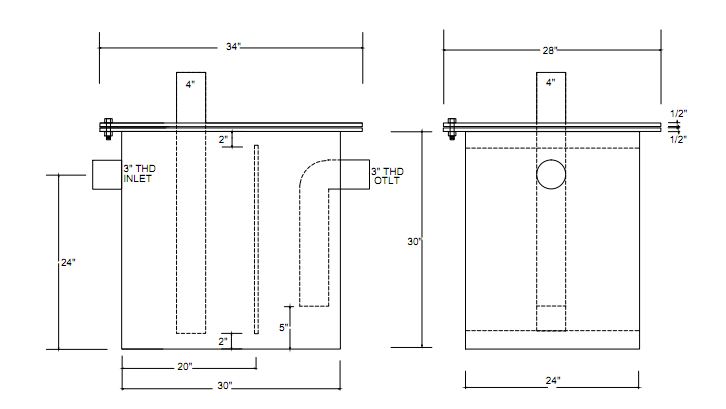
This may work in some situations, but information is being left out of this calculation that may lead to a tank too small or too large for the application. Create detailed design drawings and specifications for the grease trap, including dimensions, materials, and installation requirements. Choose the appropriate grease trap type based on the flow rate and available space. Determine the size of the trap using the grease retention capacity calculated in step 1. We offer a wide range of comprehensive services to cater to all your GREASE TRAP design needs. From initial concept development to detailed design drawings, we handle every aspect of the process with precision.


No comments:
Post a Comment